1 Introduction
Road marking machine is a special machine used to draw various road markings on high-grade highways and urban roads. It is also used to draw new markings on the old markings during the road maintenance process [1]. At present, there are many kinds of marking machines, which are applied to different occasions, but their common features are firstly through manual marking and then mechanical spraying. The manual marking has a large workload, and the work progress is slow and the accuracy is poor. In view of this phenomenon, this paper introduces the road marking machine marking guide robot, which is specially used to provide a more accurate route of the marking machine, which reduces the workload of the manual marking line and improves the accuracy of the marking.
2 outline guiding robot overview
The basic components of the line-guided robot system: the steering control system, the motor-driven crawler walking system, and the paint spraying system. The scribing-oriented robot is mainly used for the scribing guidance of the highway center line. The ultrasonic distance measuring module is installed at both ends of the robot to measure the distance between the roads on both sides of the road to the robot, and the result is processed by the Siemens S7-200PLC software program. The signal drives the motion of the DC motor, causing the robot to quickly approach the centerline and travel on the centerline. When the travel is stable, the spray gun in the paint spray system begins to spray the paint on the ground, providing the marking machine with a more accurate marking. The schematic diagram of the robot control is shown in Figure 1.
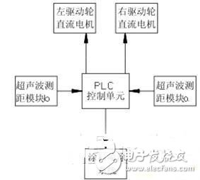
Figure 1 Schematic diagram of robot control Fig.1 The diagram of control
3 guidance control system
The basic components of the guidance control system: ultrasonic ranging module and PLC control unit.
The ultrasonic ranging module generally includes a hardware part and a software part, and the hardware part includes a control unit, an ultrasonic sensor, a transmitting and receiving circuit, and the like; the software part is a program fixed in the control unit. Ultrasonic range finder currently on the market can be slightly improved to meet the requirements of this article. The current ultrasonic range finder can reach a distance of about 10m, which far meets the requirements of this paper.
An ultrasonic ranging module is symmetrically mounted on the left and right ends of the robot, and the left and right sensors simultaneously transmit ultrasonic waves to both sides, and compare the time difference between the left and right sensors to determine whether the robot is right or left, and then control the driving wheel DC motor. The movement, thus the robot, travels on the centerline of the road. After receiving the data transmitted by the ultrasonic ranging module on both sides, the PLC control unit compares the two sets of data. If the data on the right side is small, the ultrasonic wave sent back on the right side is shorter, and the robot is biased to the right side of the center line. Then the right drive wheel rotates faster than the left drive wheel, so the adjustment is continued, and finally the robot is on the highway center line. After stabilization, the control unit stores the data returned by the ultrasonic wave at this time in the storage area. After that, the driving wheel speed of the robot travels at a constant speed at this time, and is adjusted by the data returned by the sensor in real time. The adjustment range is limited to a certain range. When the range is exceeded, the motor will start to adjust the distance between the robot and the center line to make it travel on the center line as soon as possible.
The PLC control unit software includes: a main program, a read ultrasonic ranging module data subroutine, and a motor adjustment subroutine. The program flow chart is shown in Figure 2.
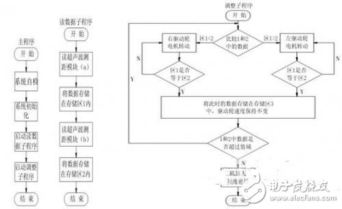
Figure 2 program flow chart Fig.2 The chart of program flow
4 motor driven crawler walking system
The way the robot moves is wheeled, walked and tracked. The walk-through structure is complex and slow to move, but the walking robot can adapt to poorer road surfaces. The wheeled structure is highly maneuverable, but it is only suitable for flat terrain. The crawler-type structure has the characteristics of stable movement, strong climbing ability, and difficulty in tipping; it overcomes the shortcomings of the wheel-moving mechanism, such as obstacle-obstacle ability, poor cross-groove ability and slippage [2-3].
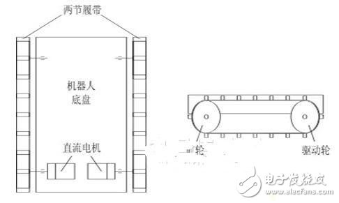
The scribe-oriented robot proposed in this paper is applied to roads with better road conditions. However, considering that the robot is looking for the mid-line travel of the road, the wheel structure is better in maneuverability, but its adaptability to the road is far less than that of the crawler. In combination with various situations, the robot adopts two parallel crawler connection modes, which are similar to the walking mechanism of the tank. The track on both sides is mounted on the front and rear wheels, and the rear wheel is driven by a DC motor, which drives the front wheels to rotate together. Its structure is shown in Figure 3. The crawler-type structural robot can not only go straight, but also can realize the in-situ steering by using the differential of the crawler. The structure is simple, and does not require a differential, a steering mechanism, or the like. The control is convenient, the turning radius is small, and the motor can provide both forward power and steering power [3].
The drive wheel DC motor selects a DC motor with a reducer with a voltage of 24V. The battery voltage is 24V, including the working battery and the backup battery. The working battery not only supplies power to the DC motor, but also supplies power to the control unit. The backup battery is used when the working battery is damaged or suddenly there is no power.
The 8-inch tablet will have a big impact on the 7-inch and 10-inch tablet market. Because the portability of an 8-inch tablet is stronger than that of a 10-inch tablet, and the usable area is larger than that of a 7-inch tablet. The most important thing is that the price is more moderate, which is much cheaper than a 10-inch tablet. It can be said that the 8-inch tablet computer has a good balance between portability and screen display area, and is more likely to be favored by the majority of users.
8 Inches Tablet Pc,Tablet Computer,8 Inch Android Tablets,8 Inch Tablet
Jingjiang Gisen Technology Co.,Ltd , https://www.jsgisengroup.com