introduction
The high frequency small signal amplifier is an amplifier that amplifies high frequency small signals with a center frequency of several hundred megahertz to several hundred gigahertz. It has important applications in communication electronic systems, and is usually used in front-end receivers for wireless communication such as broadcasting, television, communication, radar, etc., which is critical to the receiver's sensitivity, anti-interference and selectivity. influences.
The theory of high-frequency small-signal amplification is relatively simple, but the actual production is very difficult. The most prone problem is self-oscillation, and frequency selection and impedance matching between stages are also difficult to achieve. Therefore, in the circuit design, it is necessary to consider the influence of the power supply filtering, the decoupling circuit, the interstage coupling circuit, the impedance matching circuit and the matching circuit on the overall circuit.
This paper needs to design and fabricate a low-power LC resonant amplifier, which requires the following conditions: (1) resonant frequency f0=12MHz, allowable deviation ±100kHz; (2) gain not less than 40dB; (3) input resistance Rin=50Ω; 4) Insert a 40dB fixed attenuator at the input of the amplifier with a characteristic impedance of 50Ω. In order to facilitate the design of the amplifier, the NI MulTIsim circuit simulation software was used for the auxiliary design.
1 system design
The high frequency small signal amplifier is mainly composed of an attenuation network module, an LC resonance amplification module, a voltage follower module and a power module. The workflow is as follows: the signal is attenuated by the network to obtain a weak signal, and the impedance is matched by the voltage follower, and then input to the first-stage amplifying circuit. The amplified signal can also be amplified while being impedance-matched by the voltage amplifier. And through the secondary amplifier circuit, to achieve high gain, low loss LC resonance amplification. The system block diagram is shown in Figure 1:
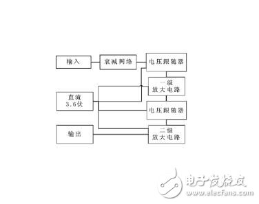
Figure 1 system block diagram
2 module analysis
2.1 Attenuation Network Module
An attenuator is a circuit that introduces a predetermined attenuation over a specified frequency range, typically indicated by the number of decibels of the introduced attenuation and the ohmic number of its characteristic impedance. Classic attenuators have π-type, T-type and bridge attenuators, and the attenuation effect is better, but for high-frequency small signals, passive attenuation networks are more suitable for π-type or T-type networks. In this paper, the π-type resistive network is selected for attenuation, as shown in Figure 2:
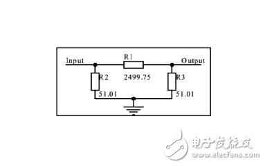
Figure 2 π-type attenuation network diagram
2.2 LC resonant amplifier module
The LC resonant amplifier consists of an LC resonant tank and an amplifier that can be used to select and amplify useful frequency signals. The resonant part uses a classical passive LC parallel resonant circuit, which is constructed by the principle that the reactance of the capacitive and inductive components changes with frequency, and the circuit is simple and stable. Another part of this module is zooming in, which is also a critical step. This design requires a 3.6V regulated power supply that consumes no more than 360mW of amplifier. According to the requirements, this paper selects the 2N2222 triode with low power consumption, which is used to amplify high-frequency small signals and achieve the gain requirement through two-stage amplification. The amplification circuit is shown in Figure 3:
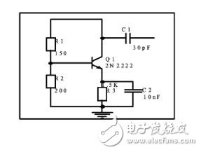
Figure 3 enlarged circuit diagram
2.3 voltage follower module
A voltage follower is an amplifier whose output voltage is the same as the input voltage, that is, the amplification factor is always less than and close to 1. The remarkable characteristics of the voltage follower are high input impedance and low output impedance, which can buffer, isolate, improve load capacity and impedance matching in the circuit. In this paper, a voltage follower is used to easily design a matching circuit between the two-stage amplifying circuits, and also has the effect of isolation. The voltage follower designed in this paper consists of an op amp OPA355 and two resistors of equal magnitude. The voltage follower circuit is shown in Figure 4:
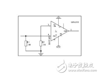
Figure 4 voltage follower circuit diagram
2.4 Power Module
In order to provide regulated power to the amplifying circuit and the following circuit, this paper designs a 3.6V regulated DC power supply with the LM317 regulator chip. The circuit is shown in Figure 5:
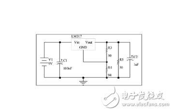
Figure 5 power circuit diagram
3 circuit simulation and testing
The overall circuit is shown in Figure 6. The simulation results are shown in Figure 7.

Figure 6 overall circuit diagram 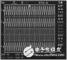
Figure 7 simulation results
The circuit uses protel drawing to make a PCB board and adds some shielding measures to prevent external interference and crosstalk between stages. The port uses a high-frequency shielded coaxial cable with an SMA connector, the high-frequency signal generator uses the EE1412F-type synthesis (DDS) function signal generator, and the oscilloscope uses the TDS2012B test. When the input signal is 12MHz, 1mVrms, the voltage gain of the two-stage amplifier is 19dB, 22dB, and the voltage gain on the final load can reach 41dB, and the waveform has no obvious distortion, which satisfies the design requirements.
I-Pulse Feeder, original and new or used one, in stock, high quality.
Material: Stainless steel
Feeder can be divided into tape feeder, tube feeder, tray feeder or stick feeder.
Feeder can be divided into original feeder and replacement feeder.
All the feeders shall be maintained during the use time
In addition, the following spare parts will be sold in our company.
SMT Feeder For Samsung
Panasonic Smt Feeder
Panasonic Feeder
Smt Machine Panasonic Feeder
Smt Feeder For Panasonic
Smt Feeder For Juki
Juki Smt Feeder
Smt Machine Juki Feeder
I-pulse Feeder
I-Pulse Feeder,Smt I-Pulse Feeder,Smt Parts I-Pulse Feeder,I-Pulse Type Feeder
Shenzhen Srisung Technology Co.,Limited , https://www.sr-smts.com