At present, most electronic devices (mobile phones, PDAs, notebooks, handheld media players, game consoles, etc.) usually need to be connected to external accessories. Therefore, these devices require dedicated logic to automatically detect the attachment of the accessory and identify its type, allowing the internal control circuitry to adjust accordingly. Adding a circuit to implement automatic detection/selection increases system power consumption, which is unavoidable. As a designer, power consumption should be minimized to ensure that the system meets the “green†environmental design goals with minimal space. To achieve this, ultra-small, micropower comparators, such as the MAX9060 series, are the best choice in the current market. These comparators are the key to helping designers control power consumption.
This article refers to the address: http://
Hardware circuit detection jack connection
We first briefly review the basic principles of automatic detection of jacks. Take the typical headphone jack circuit (Figure 1) as an example. As shown, a pull-up resistor is connected to the sense pin to generate a signal indicating whether a headset or other external device is plugged into the jack. In a typical connection, if an external device is inserted, the detection pin will be disconnected.
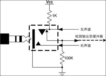
Figure 1 jack automatic detection circuit
When no accessory is inserted into the jack, the output signal is pulled high; when an accessory is inserted into the jack, the signal is pulled low. The detection signal is connected to a microcontroller port that automatically switches the audio signal between the speaker (without headphones) and the headphone speaker (with headphones).
The detection signal can be buffered by a simple transistor before the microcontroller inputs. The transistor also provides the necessary level shifting to interface with the controller. In space-constrained applications such as cell phones and PDAs, it is necessary to select transistors with a package size of no more than a few millimeters. Buffer and level shifting can also be provided with a low cost, low power, ultra-small size comparator. For example, the MAX9060 series is available in a 1mm × 1mm wafer level package and consumes only 1μA.
Headphone detection
The audio jack shown in Figure 1 is designed to handle common 3-pin audio plugs. The plug is connected to a stereo headset or a mono headset with a microphone. Stereo and mono + microphone headphones can be easily distinguished using the circuit described below. The circuit design is based on the low headphone resistance (usually 8Ω, 16Ω or 32Ω) and the high microphone resistance (600Ω to 10kΩ).
Here is a brief introduction to common audio jacks and electret microphones to help understand these circuits. In a 3-pin audio jack (Figure 2), the "plug" front end carries the left channel audio signal in a stereo headset and the microphone signal in a mono headset with a microphone. For stereo headphones, the “metal ring†position is connected to the right channel signal and the “sleeve†is grounded; for mono headphones with a microphone, the “metal ring†is connected to the input audio channel of the mono microphone, and the “sleeve†is grounded.
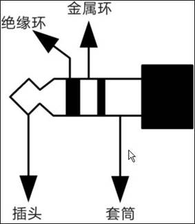
Figure 2 three-core audio jack
Electret microphone
A typical electret microphone (Fig. 3) has a capacitive element whose capacitance changes with mechanical vibration to produce a varying voltage proportional to the sound wave. Electret microphones always have an internal static charge and do not require an external power supply. However, several volts are still required to power the internal preamplifier FET. An electret microphone can be thought of as a current source that consumes a fixed current. With a very high output impedance, the high impedance is converted to the required low resistance by the FET preamplifier and connected to the subsequent amplifier. Due to its low cost, small size and good sensitivity, electret microphones are the best choice for a variety of applications, such as hands-free phone headsets and notebook sound cards.
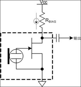
Figure 3 Electrical model of an electret microphone
The microphone is biased by a resistor (typically 1kΩ to 10kΩ) and a power supply to provide the required fixed bias current. The bias current range is from 100μA to 800μA, depending on the particular microphone and its manufacturer. The bias resistor is selected based on the connected supply voltage, bias current, and sensitivity requirements. Therefore, the bias voltage varies depending on the device and operating conditions. For example, a 2.2kΩ load resistor that draws 100μA from a 3V supply will produce a bias voltage of 2.78V. The same resistor, if absorbing 800μA, will produce a bias voltage of 1.24V. The type of earphone connected is detected according to the circuit of Figure 4. In the figure, the 2.2kΩ resistor RMIC-BIAS is connected to the low noise reference voltage (VMIC-REF) provided by the audio controller. When the audio jack is plugged into the accessory, the VMIC-REF voltage is applied through RMIC-BIAS to the equivalent resistance (not shown) between the plug and ground, producing a voltage VDETECT at the non-inverting input of the MAX9063. For stereo headphones, this resistance is small (8Ω, 16Ω, or 32Ω); for microphones, the fixed current absorbed by the current source can vary from 100μA to about 800μA due to the type of microphone, and the current value is large. Since VDETECT varies with the type of earphone inserted into the jack, it is possible to determine the type of the earphone by monitoring VDETECT through a comparator.
As shown, assuming the microcontroller's reference voltage (VMIC-REF) is 3V, a 32Ω headphone load will produce a 43mV VDETECT voltage. A 500μA fixed current microphone load will produce a voltage of 1.9V. Note that in most applications, there is a problem connecting directly to VDETECT. Assuming that the CMOS input of a typical microcontroller port requires a logic level higher than 0.7×VCC and less than 0.3×VCC, the input logic level of a 3.3V powered microcontroller should be higher than 2.3V and lower than 1V. The 1.9V level produced by the 500μA microphone load is not a valid logic "1" level. A microphone bias current of 100μA to 800μA will produce a VDETECT of 2.78V to 1.24V, and any voltage below 2.3V will not meet the controller's VIH (input high level, assuming RBIAS is 2.2kΩ). In order to obtain a voltage of 2.3V or higher, the microphone bias current must be 318μA or less. Otherwise, the 2.2kΩ bias resistor must be changed to change the detection threshold of the microphone. Since headphones with a typical load of 32Ω can easily pull the level near ground, it is easy to generate a logic low of 1V or lower. In order to detect the type of earphone, VDETECT needs to be connected to one input of the comparator to connect the reference voltage to the other input. The comparator output represents the type of headset.
The comparators of such portable earphone detection applications should be small in size and consume very low power. The comparator shown in Figure 4 measures only 1mm x 1mm and has a maximum supply current loss of only 1μA. It has strong anti-interference ability to the mobile phone frequency and provides extremely high reliability. The comparator also features internal hysteresis and low input bias current. These features make it ideal for headphone detection circuits in battery-powered products that are extremely sensitive to space and power consumption, such as cell phones, portable media players, and notebooks.
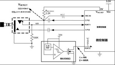
Figure 4 Comparator circuit for headphone detection
Reed switch detection
Most hands-free headsets have a switch, commonly referred to as a reed switch, that is used to answer, hang up, have a mute/hold function, and hold the current call while listening to another call. The microcontroller that controls the headset needs to detect the status of the spring switch and the connection status of the headphones, and automatically detect whether the jack is plugged into the accessory (here, the earphone) (Fig. 1). A signal is also generated to indicate the state of the compression switch. The reed switch status detection circuit consists of a 4-conductor stereo headphone (with microphone) and a parallel-connected reed switch (Fig. 5) (mono headsets are similar but 3 cores). In two different types of earphones, the plug is connected to a microphone in parallel with the pressure spring switch. As shown, the pressure spring switch exhibits a low resistance when pressed, and the microphone exhibits a high resistance when released. As described in the above-mentioned headset detection, for the microphone/reed switch detection, the interface circuit design between the microphone detection voltage and the CMOS input of the microcontroller is complicated.
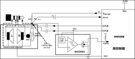
Figure 5: Reed switch detection circuit using the MAX9063 comparator
When the pressure spring switch is pressed, the voltage VDETECT (Fig. 5) is pulled down to the ground potential, and the microcontroller judges to be logic "0"; when the pressure spring switch is released, VDETECT may exceed the VIH voltage specification of the CMOS input. Depending on the RMIC-BIAS (2.2kΩ in this example) and the type of microphone in the headset, VDETECT will vary from 1.24V to 2.78V. Therefore, for different types of microcontrollers, the reed switch cannot be directly connected to the controller. Therefore, Figure 5 uses a low power comparator. The reference voltage is set according to the type of microphone actually detected, indicating the state of the compression switch. When the compression spring switch is pressed, the comparator output is pulled high; when the switch is released, it is pulled low. The MAX9060 family of comparators also offer a low-power design for hy-reed switch detection.
The oscilloscope screenshot shown in Figure 6 is obtained when the pressure switch of a mono headset is pressed. The setup is identical to the circuit in Figure 5, except that a 2.5mm universal headset for the phone is used for testing. The headphone plug has an electret microphone (with a reed switch) and the 32Ω speaker is connected to the “metal ringâ€. When powered by a 3.3V supply and biased by a 2.2kΩ resistor, the microphone absorbs a fixed bias current of 212μA. The detected VDETECT DC voltage is 2.52V (Figure 6) and the MAX9063 output is low. Pressing the compression switch will ground the VDETECT and the comparator output will be pulled high by an external 10kΩ pull-up resistor. Thus, the MAX9063 comparator in a 1mm x 1mm CSP package is ideal for detecting reed switches and accessories. The MAX9028 family of comparators is also suitable for this type of application.
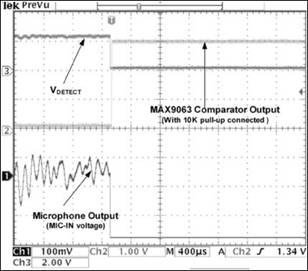
Figure 6 These waveforms are generated by an electret microphone with a reed switch, controlled by a mono headset and its internal circuitry. When the pressure switch of the mono headphone is pressed, the comparator detects a short circuit of the microphone, thereby pulling the output up to a logic high level.
Conclusion
Detecting jacks, earphones, and compression spring switches are often required in portable applications. The MAX9063 and MAX9028 family of dedicated comparators are ideal for this type of application. These devices take up very little space and consume negligible power. These comparators provide an economical solution for accessory inspection in portable applications.
Others Universal Travel Adapter
Universal Travel Adapter
Double USB Travel Plug,Single Country Plug Adapter Co., Ltd. , http://www.chtravelplug.com