To design this circuit, we must first determine how many series of HBLEDs can be driven by a 12V battery, and it needs to be designed according to the most unfavorable conditions. The most unfavorable condition is: each HBLED forward voltage 4V, the battery minimum voltage 10V, MC34063 maximum duty cycle is 5/6, under this condition, the battery through the MC34063 power conversion and current control after the highest output Voltage is
Obviously, this voltage can meet the operating voltage of two HBLEDs in series, which means that two HBLEDs can still be driven by the MC34063 at the lowest supply voltage with a 12V battery.
According to the characteristics of the HBLED and the 12V power supply voltage, two HBLEDs are connected in series, the circuit is determined as a step-down circuit topology, and the control mode selects the peak current type control and the maximum voltage limit. The HBLED drive circuit composed of MC34063 is shown in the figure below.
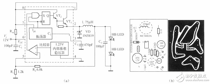
The circuit consists of MC34063, current sense resistor Rse, input bypass capacitor Ci, freewheeling diode VD, inductor L, and output filter capacitor C. The output voltage detecting resistors R1 and R2 and the driven HBLED are formed. Among them, MC34063 and VD, L, C. A buck converter is constructed.
In this circuit, the freewheeling diode should be selected Schottky diode, you can choose the common 1N5819 (1A/40V) or select other models and package Schottky diodes with rated voltage above 30V, rated current not lower than 0.SA. .
The input capacitor in the circuit above is a 100μF/16V aluminum electrolytic capacitor, which is generally satisfactory. However, from a performance point of view, the equivalent series resistance of a 100μF/16V aluminum electrolytic capacitor is at least 2Q, and the capacitive reactance at a frequency of 50kHz is only 31.8mΩ! The capacitive reactance is much lower than the equivalent series resistance. At this time, the power supply bypass effect will depend on the equivalent series resistance of the capacitor. When the 0.25A AC component flows through the bypass capacitor, an AC component of about 0.SV rms voltage is generated across the power supply, and at least 1V is generated. (peak-peak voltage) voltage fluctuations. Although this can ensure the normal operation of the circuit, it still feels less comfortable to use. If you use a 10μF/16V ceramic chip capacitor with a package of 1206 and a dielectric of X5R (retail price is about 0.2 yuan), the equivalent series resistance will be less than 10mΩ, the corresponding capacitive reactance is 0.318Q, and the total impedance is lower than 100μF. , much lower than the capacitance value of the aluminum electrolytic capacitor, the voltage spike of the input power supply will be effectively suppressed, and can be reduced to 1/10 of the aluminum electrolytic capacitor.
The choice of output filter capacitors requires consideration of how the AC component of the output current is distributed between the output filter capacitor and the HBLED. If the load is a constant current source, the AC impedance is very high and most of the AC components are shunted into the output filter capacitor. In the case of a resistive load, since the impedance of the output filter capacitor is definitely much lower than the load, the AC component current on the load is also low or low.
12vled constant current drive circuit diagram (2)This circuit first determines how many series of HBLEDs can be driven in a 24V battery, and needs to work properly under the most unfavorable conditions. The most unfavorable condition is that each HBLED has a forward voltage of 4V, the battery has a minimum voltage of 20V, and the MC34063 has a maximum duty cycle of 5/6. Under such conditions, the battery passes the power conversion and current control of the MC34063. The highest output voltage is
Obviously, this voltage can meet the operating voltage of two HBLEDs in series. In other words, with a 24V battery at the lowest supply voltage, four HBLEDs can still be driven by the MC34063.
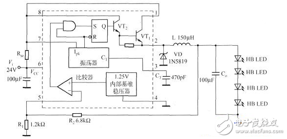
The 24V battery-powered HBLED driver circuit is shown below.
The circuit of the LED corridor light is shown below. The circuit is composed of a capacitor step-down circuit, a rectifier circuit, an LED lighting circuit, and a photoelectric control circuit.
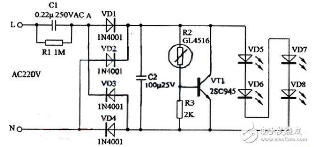
220V AC power through the capacitor C1, R1 step-down current limit after the AC voltage at A and B points is about 15V, rectified by VD1 ~ VD4. Get DC voltage of about 14V on C2 as high-brightness LED VD5 ~ VD8 The working voltage of the LED is about 14mA. Since the capacitor C1 does not consume active power, the power consumed by the bleeder resistor is negligible, so the power consumption of the entire circuit is about 15 & TImes; 0.014 ≈ 0-2 (W).
In order to further save power and extend the service life of high-brightness LEDs, a photoelectric control circuit consisting of a photoresistor R2, a resistor R3 and a triode VT1 is added to the circuit. At night, the resistance of the photoresistor R2 can reach 100K or more. The voltage across C2 is divided by R2 and R3, and the DC bias voltage supplied to the base of VT1 is very small. VT1 is cut off, which has no effect on the operation of the LED. During the daytime, due to the effect of photoelectric effect, the resistance of R2 can be Reduce to below 1OK, then VT1 is turned on and close to saturation. Since the current through C1 can only reach 15mA at maximum, the voltage on C2 can drop below 4V due to the shunt of VTl.
12vled constant current drive circuit diagram (4)High-power LED constant current drive circuit made by LM317 or MC33269
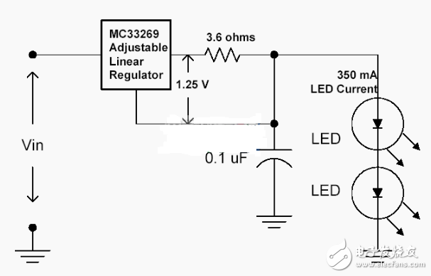
Drive current = 1.25 / 3.6 = 0.35A, a different constant current can be obtained by changing the 3.6 Ω resistor.
The input voltage must be greater than the "lamp string voltage +3V" to work reliably, and the LM317 should be equipped with a heat sink.
LED lights need to be connected in series or in parallel to work. The parallel voltage is used to drive multiple LEDs. Although the required voltage is lower, the brightness of each LED is different because the forward voltage drop of each LED is different. Different, unless a separate adjustment is used to ensure that each LED has the same brightness. Therefore, the parallel mode should ensure uniform brightness and be complicated to implement. The series connection can ensure that the current flowing through each LED is the same and the brightness is consistent, which is a commonly used structure.
When the series type driving mode is adopted, if one or several LEDs are broken and the circuit is broken (the short circuit has a small influence on the circuit and can be ignored), the circuit may be broken and cannot work normally. In order to avoid this defect, a Zener diode can be connected in parallel with each other at both ends of the LED (as shown in Figure 1). When an LED lamp bead breaks, the parallel regulator tube is put into operation, ensuring the series connection. The lamp current does not change. It should be noted that the voltage regulation value of the Zener diode is higher than the conduction voltage of the LED. Otherwise, the parallel voltage regulator will shunt a part of the current and make the LED dark or not bright.
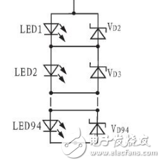
Figure 1 LED series drive circuit
In this paper, the series drive mode is adopted, and its LED linear constant current control circuit is shown in Figure 2.
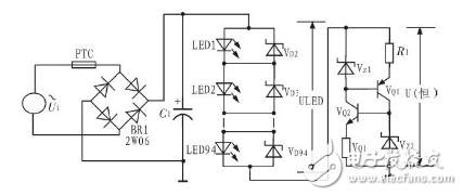
Figure 2 LED constant current control circuit
In the figure, Vz1, Vz2, VQ1, VQ2, R1, and R2 form a linear constant current source, which ensures that the current flowing through each white LED is the same, and uniform brightness is obtained. The LED driving power supply adopts the direct current rectification and filtering of the commercial power to obtain the DC working voltage of the control LED, and does not need to be boosted or stepped down, so the power driving circuit is simple and the power supply efficiency is high. The LED used is a high-brightness white LED (operating voltage range: 3.0~3.2V), which uses 94 LED beads to form an LED fluorescent lamp.
Next, the working principle analysis of the linear constant current source circuit is performed, and the circuit adopts a complementary constant current source structure at both ends, as shown in FIG.
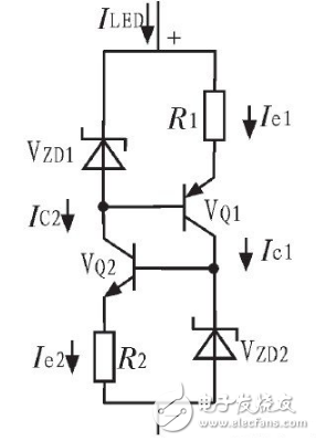
Transistor VQ1, voltage regulators Vz1 and R1 form a constant current source, which provides a stable operating current to Zener Z2, while transistor VQ2, Vz2 and R2 form another constant current source. The tube Vz1 has a stable operating current. Since the two constant current sources stabilize each other's Zener operating point, the stable voltages Vz1 and Vz2 and the total current flowing through the constant current unit are no longer changed, so that the operating current flowing through the LED can be kept constant.
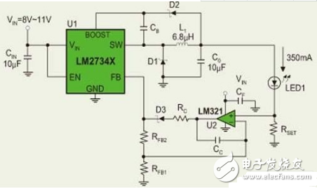
12vled constant current drive circuit diagram (6)The LM2734 is a 1A step-down regulator. The LM2734-based constant current drive circuit (shown below) uses the LM321 op amp to obtain the voltage on the sampling resistor Rset. Combined with other resistors and capacitors, it can form a complete, high-efficiency high-power LED constant current drive circuit. In actual use, some LED constant current drive circuits can directly obtain feedback voltage from the sampling resistor, as shown in the figure.
·Basic precautions
Do not put expensive oil into low-quality cartridges to avoid wastage. Most pre-filled oil cartridges have the so-called 510 thread. The oil cartridge screws onto a rechargeable battery. Some of these batteries have buttons and some heat up automatically when you pump the oil. Some batteries have multiple temperature settings and some heat up to a preset temperature; these features need to be known in advance.
·Cleaning notes
Use a suitable cleaning tool to clean them, such as activated charcoal or dried tea leaves in a used pipe to absorb the oil. It is important not to use alcohol or other boiling water to clean the pipe, and to wait until it has cooled down completely before cleaning. Otherwise, the hot stem will come into contact with the watery liquid and cause the mouthpiece tenon to loosen, thus shortening the life of the 510 cartridges.
This is what you should be aware of when using 510 cartridges. At the same time, when using 510 cartridges, there are still some vaping tips, for example, when using them, be careful not to suck too hard, will not produce smoke. When you inhale too hard, the smoke is sucked directly into your mouth and not atomized by the atomizer, so gently inhaling is more powerful and gives you a better vaping experience.
510 Cartridge Oem,Leakproof 510 Cartridge,510 Battery And Cartridges Oem,510 Cartridge
Shenzhen MASON VAP Technology Co., Ltd. , https://www.e-cigarettefactory.com