Capacitive touch interfaces are gradually replacing mechanical switches, knobs and tuning buttons in consumer, automotive, industrial and medical applications. Capacitive touch sensors are popular for their aesthetics, higher reliability, and lower production/processing costs. In addition, user interfaces based on capacitive touch sensing technology can improve the user experience and extend product life due to the absence of mechanical components that are prone to failure.
However, since capacitive touch sensors do not have tactile feedback such as mechanical buttons and switches, the transition from mechanical buttons, knobs, and tuning buttons to capacitive touch interfaces can present challenges for designers. Take the experience of typing on a keyboard as an example. After pressing and releasing a key, it can bounce off due to the action of the spring. We can feel the power of the key bounce back through the finger to confirm that the key operation has been completed. The capacitive touch interface does not provide intrinsic mechanical feedback, so the user cannot get the same feeling as the mechanical keys. Since the primary purpose is to improve the user experience, the lack of tactile feedback can present challenges to designers. Developers can use tactile technology to provide tactile feedback, improve the user experience, and increase product value.

Figure 1: Example of haptic technology implemented in a handset to provide haptic feedback.
Haptic technology is a tactile feedback technique that uses feedback from a person's touch to provide pressure, vibration, or motion to the user. A simple example of haptic technology is the vibration alert used in mobile phones and tablets. When the phone enters the vibration mode, the phone will use the actuator vibration to alert the user when there is an incoming call or message, and the user does not even need to view the screen.
Figure 2 illustrates a haptic technology implemented in a capacitive touch system. Wherein, when the user touches the capacitive touch interface, the actuator is activated to generate vibration. The user's finger can confirm the touch operation after feeling the vibration. Different touch feedback effects can be produced by controlling the voltage and frequency applied to the actuator, such as: click and double click.
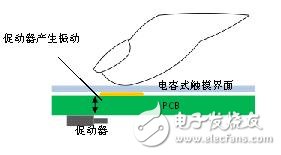
Figure 2: How haptic technology works
Implement haptic technology in a touch-based user interface:
Figure 3 illustrates haptic feedback implemented in a touch-based user interface. This system consists of the following components: touch interface touch sensing controller haptic processor actuator actuator driver
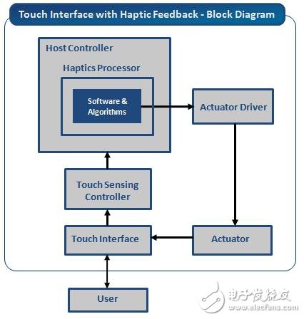
Figure 3: Block diagram of the haptic system
Touch interface: The touch interface is the area where the user interacts with the system. It consists of touch-sensitive sensors. The touch interface can be a touch screen, a touch button, or both. For example, in a mobile phone application, the touch interface is a transparent touch screen on the LCD display. In home appliance applications, the touch interface uses a copper overlay on the FR4/FPC PCB.
Touch Sensing Controller: The touch sensing controller can detect a finger touch action or a touch position of a finger on a touch surface. For touch screens, the touch controller can send touch coordinates to the application processor for processing. For touch buttons, the touch controller sends on/off status information to the application processor. Examples of touch controllers include Cypress's TrueTouch? With CapSense? Controller.
Haptic Processor: A haptic processor consists of control software and an algorithm that generates a haptic waveform driven actuator. The haptic processor can be implemented in the following ways:
â— Integration with application processor/MCU
â— With independent processor
â— Integrated with touch controller
â— Integration with actuator drive IC
* Haptic processor integrated with the application processor/MCU: In applications where the application processor/MCU has the appropriate processing bandwidth and hardware resources, the haptic processor can be integrated as shown in Figure 3. This approach eliminates the need for a dedicated haptic processor, which reduces BOM cost and saves board space.
To create different haptic effects, designers can develop custom software as well as software licenses for haptic software vendors. Developing custom haptic software requires a lot of design work, time, and additional costs. However, the advantage of custom haptic software is that designers can optimize haptic effects according to their final application needs.
To reduce design effort and time, designers can obtain licenses from suppliers' haptic software or controllers that support haptic software. An example of an MCU with a built-in haptic software library is Cypress's PSoC1 controller.
* Haptic processor integrated with an independent processor: In applications where the application processor/MCU does not have the bandwidth or resources required to integrate haptic processing functions, a stand-alone processor/MCU can be used as the haptic processor. This method is not used in most cases because it not only increases costs, but also takes up more board space.
* Haptic processor integrated with the touch controller: In addition, some touch-sensitive controllers also integrate a haptic processor. For example, Cypress's CapSense controllers have reliable capacitive touch sensing hardware and provide tactile feedback using Immersion's TouchSense haptic library. Designers can use tactile libraries to quickly achieve tactile feedback in their touch interface. Integrating a haptic processor in the touch controller can reduce the load on the application processor/MCU while providing a low-cost implementation.
* Haptic processor integrated with the actuator driver: There are a few driver driver ICs that provide an integrated haptic processor. This method is suitable for situations where haptic feedback needs to be implemented in an existing touch user interface. The actuator driver IC with integrated haptic processor in the existing touch interface minimizes the modification required for application processor/MCU firmware and board design. The application processor can send a corresponding haptic waveform generation instruction to the actuator drive IC.
Actuator: An actuator is an electromechanical component used to generate vibration and provide touch feedback to a user. The input to the actuator is provided by a haptic processor. The actuator is integrated with the touch user interface to cause the device to vibrate as the actuator gains input.
Various actuators can be employed for the haptic system. The most common ones include:
Eccentric Rotating Mass (ERM) Actuator - The ERM Actuator is a DC motor with an offset mass on the motor shaft, as shown in Figure 4. Since the motor shaft is provided with an offset mass, the offset mass has an uneven centripetal force as the motor rotates, resulting in a net centrifugal force. This centrifugal force causes displacement of the motor. Since the motor is connected to the device, the displacement of the motor can cause the entire device to vibrate. The input to the ERM motor is the DC voltage. The ERM motor has an input voltage range of 1 to 10 V and an operating current range of 130 to 160 mA. The operating frequency range is 90 to 200 Hz. The ERM motor has a low cost but provides strong vibration. However, its response time is very long (40~80ms), so it is not suitable for high quality tactile feedback. ERM motors can be used in mobile phones to provide simple haptic effects such as vibration alerts.
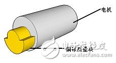
Figure 4: ERM brake structure
Linear Resonant Actuator (LRA) - LRA consists of a movable mass, a permanent magnet, a voice coil and a vibrating spring, as shown in Figure 5. When the voice coil obtains a sinusoidal input, it produces a magnetic field that interacts with the permanent magnet, causing its linear motion. The permanent magnet pushes the movable mass up and down to generate vibration. The spring connected to the movable mass returns it to its original position. The input to the LRA is a sine wave. LRA's operating voltage range is 2.5~10V, and the operating current range is 65~70mA. The typical operating frequency (resonance frequency) of LRA motor is 175Hz. Compared with ERM, LRA response time is shorter (20~30ms), and it can provide More precise, gentler vibration. LRA is often used to provide touch feedback when a virtual keyboard button is operated in a mobile phone.
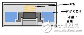
Figure 5: LRA actuator structure
Piezoelectric actuators: Piezoelectric actuators operate on the inverse piezoelectric effect - when a voltage is applied to a piezoelectric crystal, the crystal is physically deformed. This physical deformation can be used to generate vibration to provide touch feedback. The piezoelectric actuator is made of a ceramic material. The input voltage of the piezoelectric actuator is a sine wave. Piezo actuators operate from 50 to 200 Vpp and have an instantaneous current of 300 mA. Piezo actuators operate from 150 to 300 Hz. These actuators are lightweight, small, and capable of providing Fast response time (1ms), so it's suitable for high quality haptic effects on mobile phones and tablets.
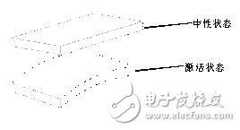
Figure 6: Piezoelectric actuator structure
Actuator Drive Circuit/IC: The output voltage/current provided by the application processor/MCU is typically insufficient to drive the actuator. For example, a typical ERM motor requires 130 to 160 mA of current. An actuator that drives this current requires an external drive circuit.
The drive circuit can be designed in the following ways:
Discrete components - The drive circuit can be constructed using discrete components such as BJT or MOSFET. Many applications use MOSFETs because they are more efficient than BJT. Figure 7 shows a simple high-side motor drive circuit. In this circuit, the MOSFET operates in the saturation region and provides a switching function. The speed of the motor is controlled by sending a PWM signal to the MOSFET input. The advantages of using a discrete component to design a driver circuit are greater flexibility and better design control. The downside is that the design is more complex and requires more board space.
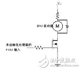
Figure 7: ERM motor drive circuit with discrete components
Dedicated Actuator Drive IC/Amplifier IC: The most common method of driving an actuator in a haptic system is to use a dedicated actuator driver or amplifier IC. The audio amplifier IC can be used for applications that use simple haptic effects, such as: vibration alert, single Hit/double click, etc. While providing advanced haptic feedback effects, a dedicated actuator drive IC can be employed. Designing such an actuator is intended to optimize the haptic feedback effect by controlling the input voltage/current of the actuator. In addition, as mentioned earlier, a few actuator drivers use a built-in haptic software library. A design that cannot achieve haptic processing in an application processor can employ a dedicated haptic driver IC.
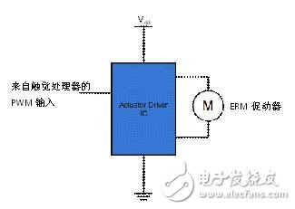
Figure 8: ERM motor drive circuit with actuator drive IC
Power Adapter,Universal Power Adapter,Usb Power Adapter,67W Usb-C Power Adapter
Guang Er Zhong(Zhaoqing)Electronics Co., Ltd , https://www.geztransformer.com