 The following is a circuit diagram of [Definition of Mutual Inductance and Unit Calculation]
 Mutual sense
1. Defining that the relationship between the flux linkages caused by the current in the coil one is linear in the coil two, the ratio between them is constant, and it is defined as mutual inductance.  For the same reason, when the current in the coil 2 is linear in the relationship between the flux linkages caused by the coil one, the ratio between them is constant, and it is defined as mutual inductance.
  .
.
2. Symbol and unit symbol—M, unit—Henry H.
Since the mutual inductance has reciprocal properties, that is, M21=M12, when only two coils are coupled, the subscript is omitted and M is used uniformly.
3. Same name end
1) Since the sense current and the mutual inductance voltage have a certain one-to-one correspondence relationship, the above-mentioned correspondence relationship is marked with the same name end ("" or "" in the engineering. In the following figure (a), 1, 2 are the same name end, and in Figure (b), 1, 2' are the same name end.
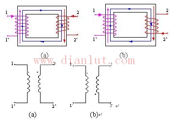
2) Experimental determination Injecting the coil with an increased inductive current, the end of the coil on which the potential is raised is the same name end.
4. The determination of the mutual inductance symbol is determined based on the reference direction of the same name terminal, that is, two inductor currents. The principle is judged that when the current reference directions of the two inductive components are both inflow (or outflow) from the same-name end of the mutual inductance, M>0; when the current reference directions of the two inductive components flow in one end from the same name, the other flows out from the same name end When, M<0.
As shown in the figure below, M1>0, M2<0, M3<0, M4>0 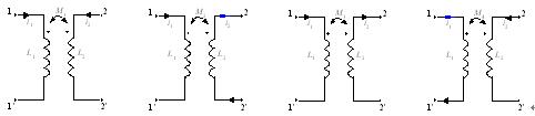
4. Coupling coefficient k
The engineering quantitatively describes the degree of coupling tightness of the two coupled coils, and defines the geometric mean of the ratio of the mutual flux linkage and the self-inductance flux of the two coils as the coupling coefficient, denoted as k: 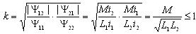
Antenk MICRO USB :Micro USB is a miniaturized version of the Universal Serial Bus (USB) interface developed for connecting compact and mobile devices such as smartphones, MP3 players, GPS devices, photo printers and digital cameras.
Micro USB connectors exist or have existed in three forms: micro A, micro B and micro USB 3. USB 3 micro is much like micro B, but with an additional pin group on the side for twice the wires, enabling USB 3's greater speed. Like standard USB, the micro versions are plug-and-play and hot-swappable.
Micro Usb2.0 B Female,Micro Usb SMT Dip,Usb SMT Dip with Flange,Micro Usb B Female SMT Dip
ShenZhen Antenk Electronics Co,Ltd , https://www.antenksocket.com