With the improvement of modern vehicle comfort and intelligence level, more and more intelligent electronic control systems are being used, and the electric load of the whole vehicle is gradually increasing. Therefore, it is more important to ensure the normal working state of the vehicle generator. Especially in vehicles that use an electronic control system, once the power supply system fails, it can only be parked. The following sections analyze the potential hazards and improvement measures of the currently widely used vehicle alternator charging indicator lines.
This article refers to the address: http://
The circuit structure of the domestic automotive alternator is basically the same, which is composed of the generator winding (stator), the excitation winding (rotor, some models use permanent magnet rotor), the rectifier tube, the voltage regulator (the excitation current can be adjusted, The output voltage can also be adjusted directly by the switching element. The regulator can be integrated into the generator or externally. There are generally a charge output (+b) terminal, an indicator light (d+) terminal, a neutral point (n) terminal, and a ground (e) terminal on the housing, wherein the neutral point terminal is not necessary. The generator's charge indicator circuit structure is similar: the additional three diodes output DC voltage to control the charge indicator. However, such a widely used charging indicating circuit has a defect that when the internal fault of the generator cannot be charged, the charging indicating circuit can be intact, and thus the indicator light is normally extinguished, indicating that charging is being performed. In fact, the battery is supplying power to the entire vehicle until the battery is exhausted and the vehicle cannot be started. The following is an analysis of the Dongfeng eq1021h15q gasoline pickup truck charging circuit (generator part number: 31qm-01010 / 14v80a), and find out the improvement method.
First, the analysis of the work process
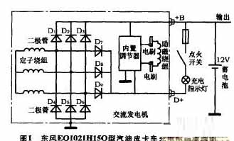
As shown in Fig. 1, the diodes d1 to d6 are high-power main rectifier tubes, which constitute a 3-phase star rectifier circuit, which supplies power and charging for the entire vehicle. The medium power diodes d7 to d9 are dedicated rectifiers for the regulator and the charging indicating circuit, and the output 14v DC voltage (d+) is isolated from the main output (+b). When the generator is running, both the +b and d+ terminals output 14v DC voltage. It can be seen from Fig. 1 that when the main rectifiers d1 to d3 are disconnected due to a fault and the other rectifiers are normal, the charging indicating circuit can still work normally. That is, when the d+ terminal outputs 14v DC voltage, the main output terminal (+b) does not necessarily have an output. In this way, once the battery is exhausted, the vehicle will not start. (There are several pickup trucks in the company that are anchored in the wild because of the exhaustion of the battery, so the rescue vehicle has to send a new battery to save the emergency).
Second, improvement measures
It can be seen from the above analysis that the direct and reliable method for judging whether the generator generates electricity is to detect the output charging current of the main output (+b) terminal. The detection of d+ terminal voltage is only an indirect method, although in most cases the output of d+ and +b is synchronous (such as stator winding, rectifier d4 ~ d6 damage caused by no power generation, d + and + b will have no output voltage at the same time) However, the above analysis has not been synchronized, and once the battery is exhausted, it may cause serious consequences. Here are a few examples of improvements that can be taken.
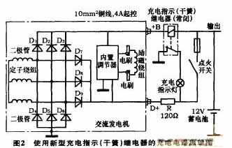
1. Developed a new charge indicator (reed) relay. The function of this (reed) relay is also to indicate the charging output of the generator, but the primary coil is connected in series in the +b output circuit to directly detect the charging current (can be called current type reed relay. Commonly used are Voltage type), see Figure 2. This relay has two key parameters: the primary coil rated voltage drop and the primary coil rated operating current. The resistor r provides the initial excitation current for the generator (the generator is independently powered by the regulator without the resistor r). This line is relatively simple.
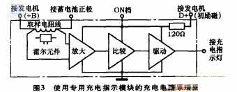
2. Development uses a dedicated charging indicator module. This module detects the generator charging current through the internal sampling resistance line (the Hall element can also be used to detect the magnetic field generated by the sampling resistor line). After amplification and comparison, the indicator light is driven. The block diagram is shown in Figure 3. This module can also be integrated inside the regulator, simplifying installation and increasing reliability.
3. Use the charge indicator ammeter. The ammeter can indicate the charging and discharging current of the battery, and has the advantages of being intuitive and accurate, but the arrangement is difficult, the line loss is increased, the cost is increased, and modern vehicles are rarely used.
4. Use a voltmeter. The voltmeter can monitor the battery voltage at any time, and can also intuitively reflect the charge and discharge of the battery. According to the actual measurement, the no-load voltage of the charged battery that can start the vehicle smoothly is 12.5v~13v, and the battery terminal voltage can rise to 14v after the engine is running (14v voltage is limited by the generator regulator, regardless of the engine speed. At the same time, open Headlights, air conditioners will not cause 14v voltage drop). If the generator can't generate electricity, then the battery terminal voltage will gradually drop on the basis of the no-load voltage after the engine is started (the whole vehicle power supply is taken from the battery), and there will be no rise. Therefore, the change of the battery terminal voltage before and after the generator operation directly reflects whether the generator generates electricity (if the voltage rises but cannot reach 14v, it indicates that the generator's power generation capacity is degraded and there is a fault). The voltmeter can be connected to any suitable power supply terminal for flexible layout without increasing line loss. At the same time, an alarm buzzer can be set inside the voltmeter, and an alarm sounds when the voltage is lower than 12v.
It can be seen from the internal structure of the generator that the charging circuit must not be disconnected while the generator is running. Otherwise, a large current (tens of amps) that suddenly drops will generate an abnormally high voltage across the stator winding, breaking through the rectifier and regulator.
Third, the practical application
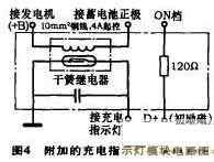
Comprehensive production difficulty, development cycle, practical effects and other factors, and the use of improved measures 1, 4, made an additional indicator module, the circuit shown in Figure 4. The reed relay's rated contact operating current is set to 4a (this current is too large to make the charging indicator not extinguish when the engine is running low), which can sensitively indicate the generator's charging current. However, the circuit using the reed relay has two disadvantages: 1. When the generator's power generation capacity drops (a rectifier current failure can only output a small current below 10a. It is not completely unable to charge), and the line still indicates normal. Charging (when the vehicle has a large electric load, it will still cause the battery to lose power); 2 When the battery full voltage is close to 14v, the charging current will drop to less than 4a. At this time, the charging indicator lights up to indicate that there is no charging current, which will make people Misunderstanding that the generator cannot be charged. To this end, a voltmeter is added to the combination meter, and together with the charging indicator lamp, a complete charging indicating line is formed. The working process is analyzed as follows.
1. The charging indicator lights up and the voltmeter shows that the voltage is lower than 13.8v, indicating that the generator cannot be charged (generator damage).
2. The charging indicator is off and the voltmeter shows that the voltage is lower than 13.8v, indicating that the generator is charging normally.
3. The charging indicator lights up and the voltmeter shows that the voltage is higher than 13.8v, indicating that the battery is full and the generator does not output excessive charging current (generator is normal).
4. The charging indicator is off and the voltmeter indicates that the voltage is higher than 13.8v, indicating that the generator regulator is damaged and cannot limit the charging voltage. The battery will be overcharged and damaged (generator damage).
This line has a good response after loading in small batches, eliminating the hidden dangers of accidents.
Electronic Cigarette,Largest E-Cig Oem,China E-Cig Oem,Vape Pen Oem,Vape Device Oem
Shenzhen MASON VAP Technology Co., Ltd. , https://www.e-cigarettefactory.com