Dual 16-bit 125Msps analog-to-digital conversion circuit designed with LTC2185
The LTC2185 is a dual 16-bit 125Msps low-power analog-to-digital converter (ADC) with two simultaneous sampling, 76.8dB SNR, 90dB SFDR, single-supply 1.8V operation, 185mW/154mW/100mW per channel, CMOS, DDR CMOS or DDR LVDS output, input range 1VP-P to 2VP-P, 550MHz full power bandwidth S/H, mainly used in communication, cellular base station, SDR, portable medical image, multi-channel data acquisition and non-destructive testing.
LTC2185 applications: communications; cellular base stations; software-defined radios; portable medical imaging; multi-channel data acquisition systems;
Main features of LTC2185: channel simultaneous sampling ADC; signal-to-noise ratio 76.8 dB; 90 dB SFDR; low power: 370 mW / 308 mW, 200 mW total; 185 mW, 154 mW / 100 mW per channel; single 1.8 V power supply; , CMOS, or DDR DDR LVDS output; select input range: 1 to 2 VP-P VP-P; 550 MHz full power bandwidth S / hour; optional data output Randomizer; optional clock cycle working stabilizer; , trim mode; SPI serial port configuration; (9 mm × 64 pin 9 mm) QFN package.
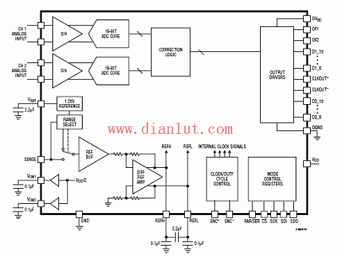
Figure 1. Block diagram of the LTC2185 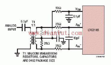
Figure 2. LTC2185 uses a transformer 5MHz-700MHz analog input circuit diagram 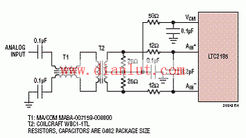
Figure 3. Front-end circuit diagram of the LTC2185 input frequency from 5MHz to 150MHz 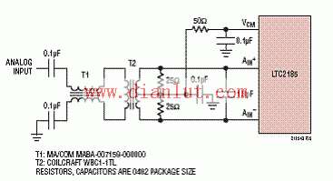
Figure 4. Front-end circuit diagram of the LTC2185 input frequency from 150MHz to 250MHz 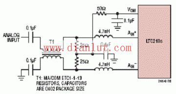
Figure 5. LTC2185 front-end circuit diagram with input frequency greater than 250MHz 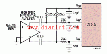
Figure 6. Front-end circuit diagram of the LTC2185 using a high-speed differential amplifier. 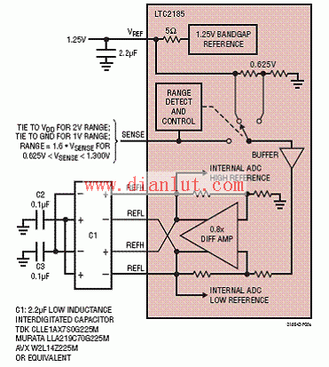
Figure 7. LTC2185 reference circuit diagram 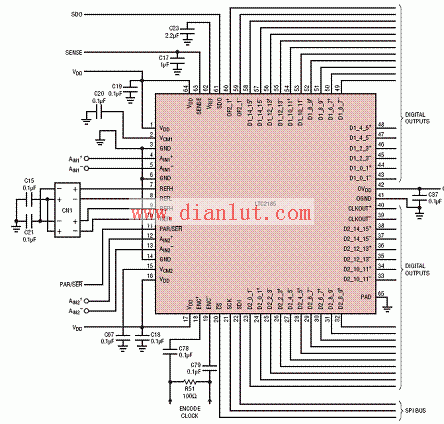
Figure 8. LTC2185 application circuit diagram 
Figure 9. LTC2185 application circuit PCB layout (top view)
ZGAR Aurora 3000 Puffs
ZGAR electronic cigarette uses high-tech R&D, food grade disposable pod device and high-quality raw material. All package designs are Original IP. Our designer team is from Hong Kong. We have very high requirements for product quality, flavors taste and packaging design. The E-liquid is imported, materials are food grade, and assembly plant is medical-grade dust-free workshops.
Our products include disposable e-cigarettes, rechargeable e-cigarettes, rechargreable disposable vape pen, and various of flavors of cigarette cartridges. From 600puffs to 5000puffs, ZGAR bar Disposable offer high-tech R&D, E-cigarette improves battery capacity, We offer various of flavors and support customization. And printing designs can be customized. We have our own professional team and competitive quotations for any OEM or ODM works.
We supply OEM rechargeable disposable vape pen,OEM disposable electronic cigarette,ODM disposable vape pen,ODM disposable electronic cigarette,OEM/ODM vape pen e-cigarette,OEM/ODM atomizer device.

Aurora 3000 Puffs,Pod System Vape,Pos Systems Touch Screen,Empty Disposable Vape Pod System,3000Puffs Pod Vape System
ZGAR INTERNATIONAL TRADING CO., LTD. , https://www.zgarpods.com